Description
Application
These cables are used as measuring and control cables in tool machinery, plant installation, power stations and in data equipment. The braided screen offers best possible protection against mechanical damage. The galvanised coating on the steel wire braiding not only helps protect against corrosion, but also notably improves the soldering performance.
Standard
Adapted to DIN VDE 0245, 0281, 0293, 0295.
Technical Data
- Nominal Voltage: Uo / U 300 / 500V
- Insulation Resistance: Min. 20 GΩ x cm
- Temperature Range: Flexing -5°C to +70°C. Fixed installation -30°C to +70°C
- Minimum Bending Radius: Flexing 20 x cable ø. Fixed installation 6 x cable ø
- Test Voltage: 4000V
- Breakdown Voltage: Min. 8000V
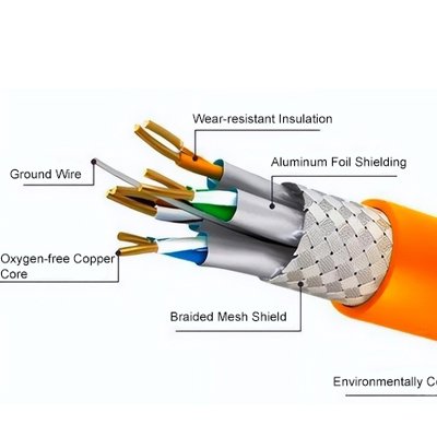
Cable Construction
- Bare copper, fine wire conductors, to EN 60228 Cl.5.
- Core insulation of PVC TI2, EN 50363-3.
- Black Core with continuous white numbering to DIN VDE 0293.
- Green/Yellow earth core in outer layer (3 cores and above).
- Cores stranded in layers with optimal lay-length.
- Special PVC inner jacket.
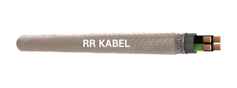
- Galvanized steel wire screening.
- Special PVC outer jacket.
- Colour transparent (also available in grey).
Properties
- The clear transparent PVC outer sheath accentuates the optical view of the galvanized steel wire braid
- PVC self-extinguishing and flame retardant according to EN 60332-1-2
- JZ-YSY Grey(RAL 7001) is also available in oil resistant variant as JZ-YSY OR. The outer sheath provided here is of special PVC TM5 to BS EN 50363 -4.1.
Note
- *G = With green/yellow earth core
- x = Without green/yellow earth core
- For current ratings to DIN VDE 0298-4 refer table no. 12-3 of Appendix
Application
These cables are used as measuring and control cables in tool machinery, plant installation, power stations and in data equipment. The braided screen offers best possible protection against mechanical damage. The galvanised coating on the steel wire braiding not only helps protect against corrosion, but also notably improves the soldering performance.
Standard
Adapted to DIN VDE 0245, 0281, 0293, 0295.
Technical Data
- Nominal Voltage: Uo / U 300 / 500V
- Insulation Resistance: Min. 20 GΩ x cm
- Temperature Range: Flexing -5°C to +70°C. Fixed installation -30°C to +70°C
- Minimum Bending Radius: Flexing 20 x cable ø. Fixed installation 6 x cable ø
- Test Voltage: 4000V
- Breakdown Voltage: Min. 8000V
Cable Construction
- Bare copper, fine wire conductors, to EN 60228 Cl.5.
- Core insulation of PVC TI2, EN 50363-3.
- Black Core with continuous white numbering to DIN VDE 0293.
- Green/Yellow earth core in outer layer (3 cores and above).
- Cores stranded in layers with optimal lay-length.
- Special PVC inner jacket.
- Galvanized steel wire screening.
- Special PVC outer jacket.
- Colour transparent (also available in grey).
Properties
- The clear transparent PVC outer sheath accentuates the optical view of the galvanized steel wire braid
- PVC self-extinguishing and flame retardant according to EN 60332-1-2
- JZ-YSY Grey(RAL 7001) is also available in oil resistant variant as JZ-YSY OR. The outer sheath provided here is of special PVC TM5 to BS EN 50363 -4.1.
Cable Design Parameters
Please complete the part numbers for these cables by adding the suffix (in place of ‘z’) for the sheath colour required:
3 – grey (RAL 7001), 6 – transparent. For oil resistant sheath (grey), kindly add ‘OR’ after the part nos.
| Part Number | No. of Cores & Nominal Cross Sectional Area (Sq. mm) | Approx. Cable Diameter (mm) | Approx. Copper Weight (kg/km) | Approx. Cable Weight (kg/km) |
|---|---|---|---|---|
| 03110101021z | 2 x 0.5 | 8.0 | 9.5 | 99 |
| 03110102011z | 3G 0.5 | 8.3 | 14.0 | 109 |
| 03110103011z | 4G 0.5 | 8.8 | 19.0 | 123 |
| 03110104011z | 5G 0.5 | 9.3 | 24.0 | 153 |
| 03110105011z | 7G 0.5 | 9.9 | 33.5 | 171 |
| 03110106011z | 10G 0.5 | 11.8 | 47.5 | 246 |
| 03110107011z | 12G 0.5 | 12.1 | 57.0 | 263 |
| 03110108011z | 14G 0.5 | 12.6 | 66.5 | 289 |
| 03110109011z | 18G 0.5 | 13.8 | 85.5 | 313 |
| 03110110011z | 21G 0.5 | 14.4 | 100.0 | 354 |
| 03110111011z | 25G 0.5 | 14.8 | 118.5 | 391 |
| 03110112011z | 30G 0.5 | 16.5 | 142.5 | 462 |
| 03110113011z | 40G 0.5 | 18.3 | 190.0 | 582 |
| 03110114011z | 61G 0.5 | 21.5 | 289.5 | 833 |
| 03110143021z | 2 x 1.5 | 9.6 | 29.0 | 159 |
| 03110144011z | 3G 1.5 | 10.0 | 43.5 | 181 |
| 03110145011z | 4G 1.5 | 10.7 | 58.0 | 206 |
| 03110146011z | 5G 1.5 | 11.5 | 72.5 | 243 |
| 03110147011z | 7G 1.5 | 12.3 | 101.0 | 302 |
| 03110148011z | 8G 1.5 | 13.5 | 116.0 | 334 |
| 03110149011z | 12G 1.5 | 15.5 | 173.5 | 449 |
| 03110156011z | 3G 2.5 | 11.5 | 61.0 | 228 |
| 03110157011z | 4G 2.5 | 12.4 | 82.0 | 290 |
| 03110158011z | 5G 2.5 | 13.3 | 102.0 | 341 |
| 03110163011z | 3G 4 | 12.7 | 96.0 | 296 |
| 03110164011z | 4G 4 | 13.7 | 128.0 | 345 |
| 03110165011z | 5G 4 | 14.9 | 159.5 | 410 |
| 03110167011z | 4G 6 | 16.0 | 191.5 | 540 |
| 03110168011z | 5G 6 | 17.3 | 239.5 | 570 |
| 03110170011z | 4G 10 | 18.4 | 326.0 | 710 |
| 03110171011z | 5G 10 | 20.1 | 407.5 | 865 |
| 03110173011z | 4G 16 | 22.0 | 543.0 | 1050 |
| 03110174011z | 5G 16 | 24.1 | 678.5 | 1280 |
| 03110175011z | 4G 25 | 26.4 | 844.5 | 1620 |
| 03110176011z | 5G 25 | 29.0 | 1055.5 | 1970 |
| 03110177011z | 4G 35 | 30.6 | 1189.0 | 2205 |
Note
- *G = With green/yellow earth core
- x = Without green/yellow earth core
- For current ratings to DIN VDE 0298-4 refer table no. 12-3 of Appendix